Software Rev 1.00
1-MAF Translator
2-Male spade terminal
2-TAP connector
3 - small spade terminals
1-instruction manual
Introduction:
The MAF Translator is a conversion interface to allow the use of late model GM Mass Airflow (MAF) sensors on Toyota MK-III vehicles.† The late model GM MAF sensors offer lower intake restriction than stock which boosts horsepower and improves turbo response.† Inside the Translator, there are several user adjustments which permit tuning of the airflow signal to the ECU (Engine Control Unit).† Increasing or decreasing the airflow signal sent to the ECU will cause the ECU to deliver more or less fuel to the engine.† The MAF Translator can also be used to correct for larger or smaller than stock fuel injectors.† The controls in the Translator allow adjustments under different operating conditions (idle, cruise, boost, and rpm) to allow the user to tune for optimum fuel efficiency or performance.†† The Translator also has an AUX adjustment for controlling fuel differently when a trigger wire is energized (to compensate for other fueling equipment such as N2O, Propane, or Alcohol injection.) The Translator has a HAC simulation output to eliminate tuning changes caused by changes in altitude.
Installation:
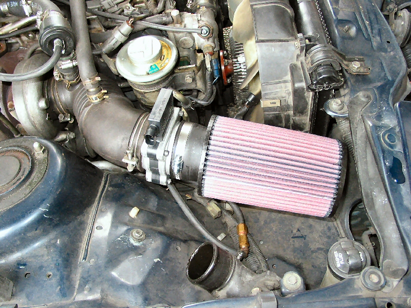
These instructions are for a conventional suck through setup, basically a replacement for the stock AFM (Air Flow Meter) ñ while a blow through setup is well within the capacity of the MAFT setup, it requires some custom work that will be noted later in this document.† This also uses the Impala SS MAF sensor, simply because it easily fits in the end of the stock accordion pipe on the front of the turbo.† Larger sensors can easily be used with adapters, or completely custom pipes.
1. Remove the upper intercooler pipe from the 3000 pipe to the fender pipe.† This isnít absolutely necessary, but it makes it much easier to work and itís virtually no effort.
2. Unplug and remove the stock Karmen Vortex based AFM (Air Flow Meter).†
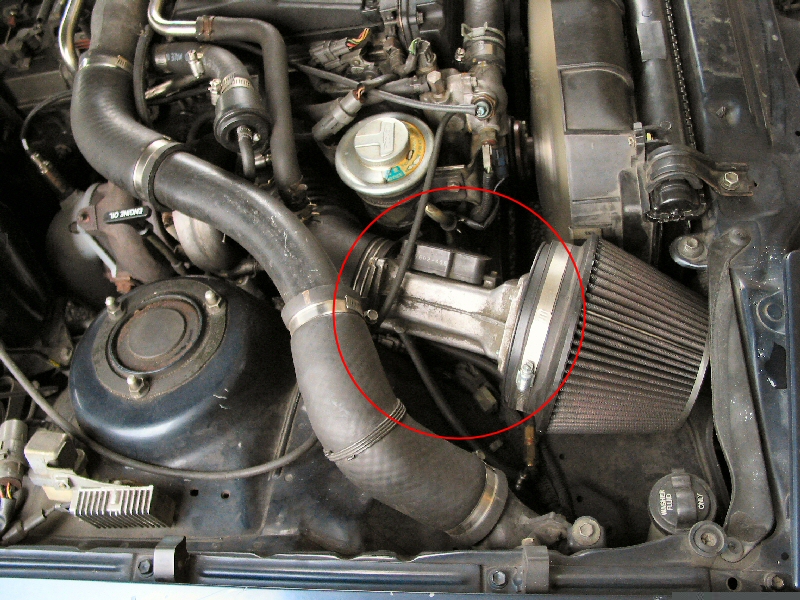
3. Install the MAF sensor in the intake tract.
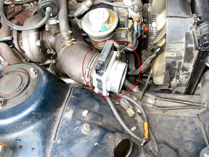
4. Add an air filter to the input end of the MAF sensor.† I used a K&N filter, I visited my local auto supply place and dug through their shelves until I found one that fit.
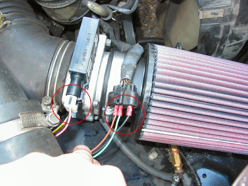
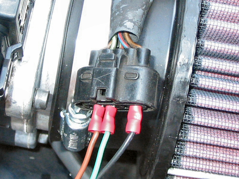
5. Plug the Translator into the MAF sensor, and the Black, Green, and Brown wires from the MAFT into the stock AFM plug using the 3 small spade terminals as follows:
a. Black - ground (E2).† AFM connector, Pin #1,† Brown wire with black dot.
b. Green - Airflow signal (KS).† AFM connector, Pin#3,† Pale green wire, brown dot ,black stripe
c. Brown - Air temp signal (THA).† AFM connector, Pin#4, Pale green wire, brown dot
6. The remaining MAFT wires are connected to the vehicle as follows:
a. Pink - Switched +12volt power source.† I used the cig lighter source; there are several choices for this wire.
b. White - RPM signal, connect the line leading from the ECU to the igniter. It's called 'IGT'.† I connected this at the ECU, using the following steps:
i. Remove the exterior of the glove box by removing two marked screws from underneath.
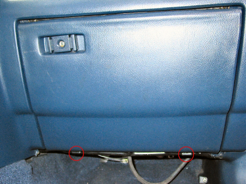
ii. Remove the interior of the glove box by removing the 5 marked screws.
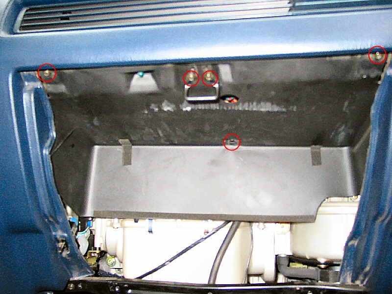
iii. Remove the ECU by removing the two marked screws.

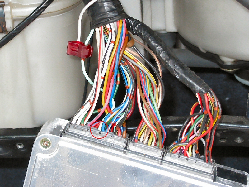
iv. Locate the IGT wire at the ECU.
1. Pre 89 vehicles:

Actual photo goes here
2. 89+ vehicles:

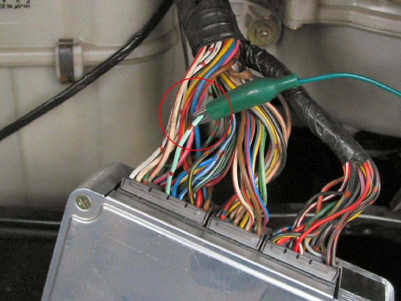
v. Splice into the IGT wire at the ECU with the provided TAP connector.
c. Gray - HAC simulator signal.† Connect to HAC signal wire at glove box / ECU. (optional) Note, if you don't live in an area with large hills, this step is not absolutely necessary.† The ECU has the ability to compensate for moderate altitude shifts without the HAC simulation connected.
i. Pre '89 cars, the HAC (High Altitude Compensation) is located behind the glove box.† Connect the gray Translator wire to the HAC sensor signal wire, and unplug the HAC.
Actual photo goes here
ii. In 89+ cars, this sensor is integral to the ECU.† This can still be connected by someone with moderate ability using a soldering iron.† Instructions for this are currently under construction.†††
Actual photo goes here
d. Purple - this wire triggers the AUX dial when the unit is set to RPM mode.† Switch 12 volts to this wire to enable the aux adjustment.
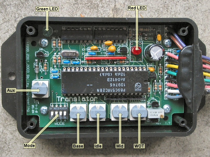
Controls:
The Translator has the following controls:
|
Control |
Description |
Initial Setting* |
|
Mode switch |
a 4 section ìdip switchî for setting MAF size, startup enrichment on / off, and MAF / RPM modes for tuning. Turn the engine off when making changes to the MODE switch. |
All off |
|
Base dial |
this 16 position (0-F) dial is used to set the general airflow scaling.† This adjustment affects the entire operating range and is generally used to match the Translator and MAF to the selected injector size. |
2 |
|
Idle dial |
This 16 position (0-F) dial is used to adjust the airflow signal during engine idle conditions.† It can also be used to compensate for modified PCV (crankcase vent) and fuel pressure setups. |
0 |
|
Mid dial |
This 16 position (0-F) dial is used to adjust the airflow signal during moderate acceleration conditions.† |
0 |
|
WOT dial |
This 16 position (0-F) dial is used to adjust the airflow signal during heavy acceleration conditions. |
0 |
|
Aux dial |
16 position (0-F) dial is used to adjust the airflow signal during heavy† acceleration conditions when the purple TRIGGER wire is activated.† This mode is active above 8 psi boost (approximate) The AUX dial is also used for selecting the base injector and Fuel Cut settings. |
0 |
|
Green LED |
OFF = No signal from MAF†† DIM = Idle, Part throttle/cruise† (In RPM mode, the green LED turns on at 1000 RPM) ON = MID |
n/a |
|
Red LED** |
OFF = No WOT modes are operating DIM= WOT mode ON = WOT mode and AUX Trigger is activated. |
n/a |
* Initial Settings listed are for stock 440cc injectors with no frequency cap on the signal sent to the ECU.
** The Red LED will blink when the controls are adjusted to indicate the unit accepted the adjustment.
Initial Setup:†
(Turn the car off when
making changes to the MODE switch)
1. Set the Mode switch per the vehicle configuration above,† ensure Mode switch #4 is OFF
1 ñ See Table below
2 ñ See Table below
3 ñ turn ON to enable startup enrichment.
4 ñ OFF = MAF mode (part throttle tuning), ON = RPM mode (WOT fine tuning)
|
MAF Selection |
||
|
Mode Switch |
|
|
|
1 |
2 |
|
|
OFF |
OFF |
3" MAF |
|
ON |
OFF |
3.5" MAF |
|
OFF |
ON |
85mm MAF |
|
ON |
ON |
Extreme MAF |
2. Select the injector size from the table below and set the AUX and BASE knobs accordingly.† The Aux dial controls an optional frequency cap ñ so if you pick an Aux setting of C, for instance, the MAFT will cap the signal it sends the ECU at 1400 Hz.† This will effectively disable the stock Fuel Cut.† CAUTION!† Disabling the stock Fuel Cut can cause serious damage to your engine if you do not have a method of providing and monitoring extra fuel!† Do *not* use this setting unless you know what you are doing.
|
|
AUX = 0 |
AUX = 1 |
AUX = 2 |
AUX = 3 |
|
1500 limit |
AUX = 4 |
AUX = 5 |
AUX = 6 |
AUX = 7 |
|
1450 limit |
AUX = 8 |
AUX = 9 |
AUX = A |
AUX = B |
|
1400 limit |
AUX = C |
AUX = D |
AUX = E |
AUX = F |
|
BASE = 0 |
420 |
570 |
720 |
870 |
|
BASE = 1 |
430 |
580 |
730 |
880 |
|
BASE = 2 |
440 |
590 |
740 |
890 |
|
BASE = 3 |
450 |
600 |
750 |
900 |
|
BASE = 4 |
460 |
610 |
760 |
910 |
|
BASE = 5 |
470 |
620 |
770 |
920 |
|
BASE = 6 |
480 |
630 |
780 |
930 |
|
BASE = 7 |
490 |
640 |
790 |
940 |
|
BASE = 8 |
500 |
650 |
800 |
950 |
|
BASE = 9 |
510 |
660 |
810 |
960 |
|
BASE = A |
520 |
670 |
820 |
970 |
|
BASE = B |
530 |
680 |
830 |
980 |
|
BASE = C |
540 |
690 |
840 |
990 |
|
BASE = D |
550 |
700 |
850 |
1000 |
|
BASE = E |
560 |
710 |
860 |
1010 |
|
BASE = F |
570 |
720 |
870 |
1020 |
3. Ensure the ECU is reset (disconnect the vehicle battery or pull the EFI fuse from the engine bay fuse box for a minute or so)
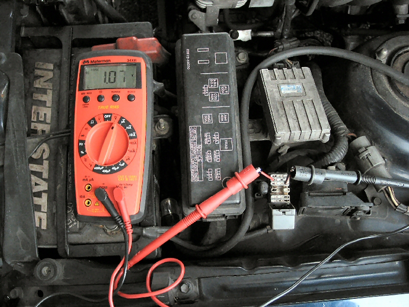
4. Connect any Vf logging equipment and start the vehicle.† This can be done with a digital voltmeter, simply plug into the Vf1 and E1 ports on your diagnostic plug and set your meter to measure 5 volts.
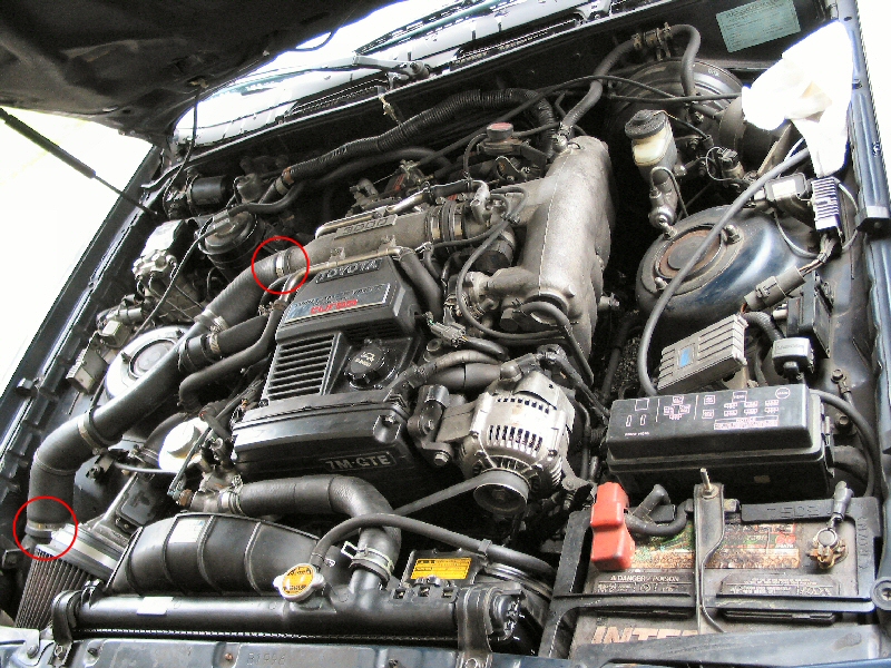
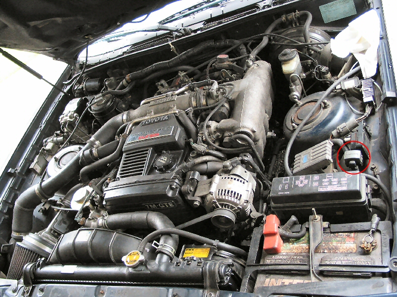
a. Locate your diagnostic plug.† This should be close to your battery, as shown below.
b. Open the diagnostic plug and locate the Vf1 & E1 terminals.
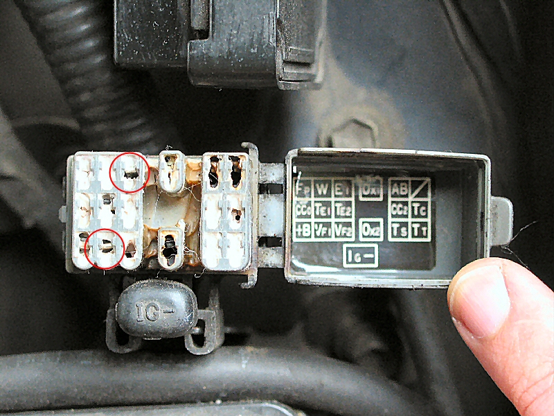
c. Connect your digital voltmeter to these terminals and set to measure 5 volts, preferably with one decimal accuracy.† I would recommend that you wire in an extension so you can monitor the Vf frequency from inside the cabin, as some of the tuning must by done either on the road or on a dyno.
5. Start the vehicle.
6. The vehicle will enter closed loop within a minute or so of starting.†
7. Make sure that the idle O2 sensor is not overly lean as indicated by a constant low voltage signal or overly rich as indicated by a constant high voltage at warm idle.† If needed, adjust the idle knob as shown in the Idle, Mid, and WOT tables below.
MAF Mode Idle, Mid, and WOT all follow the following table
|
Dial Setting |
% flow change |
|
Dial Setting |
% flow change |
|
0 |
0 |
|
8 |
35% |
|
1 |
5% |
|
9 |
-35% |
|
2 |
10% |
|
A |
-30% |
|
3 |
15% |
|
B |
-25% |
|
4 |
20% |
|
C |
-20% |
|
5 |
25% |
|
D |
-15% |
|
6 |
30% |
|
E |
-10% |
|
7 |
35% |
|
F |
-5% |
8. Make a test drive and monitor the Vf signal.
9. Adjust the BASE knob to keep the Vf signal near midrange during steady state driving (35-45 mph).† To lean out the entire fuel curve, set the AUX/BASE to a larger injector size. To richen the fuel curve, set the AUX/BASE to a smaller injector size.
10. You will need to readjust idle if you make changes to the base setting
11. Perform some light accelerations in 4th gear starting at about 2000 RPM and watch what the Vf signal does as the airflow value climbs.† Adjust the MID control if the Vf signal value at moderate flows is significantly different than at low flow.
12. Increase the acceleration to half throttle or so and watch to be sure you stay rich before trying WOT.
13. Make some WOT runs and watch the O2 readings on a datalogger, O2 monitor, EGT gauge, or Wideband AF Monitor.† Use the WOT knob to adjust the fuel delivery.† A little too rich is better than a little too lean.
14. Each change in these settings of stored in Flash memory so the dials can be used for RPM mode below.
Some notes about the
Vf signal:
The Toyota ECU outputs this signal to explain how it is currently modifying the base fuel map.† There are only 5 settings, listed below:
|
Vf voltage |
Fuel adjustment |
|
0v |
Reducing lots of fuel from base maps |
|
1.25v |
Reducing some fuel from base maps |
|
2.5v |
No change from base maps |
|
3.75v |
Adding little bit of fuel from base maps |
|
5v |
Adding lots of fuel from base maps |
Furthermore, The Vf will go to 0 volts when decelerating, and when accelerating and going into open loop (richer than 14.7 A/F). Ignore the Vf output at idle.
Don't worry about the decimal points in
the voltage. There are only 5 steps in the Voltage output, the decimal points
do not mean much and will bounce around due to wire resistance, heat,
alternator output, and half a hundred other reasons.
RPM Mode, WOT Fine Tuning
setup:
∑ Once the BASE settings are done, switch MODE 4 ON.† This will save the base settings and allow the use of the dials for RPM/WOT tuning. (wait at least 10 seconds after your last base adjustment, then turn the ignition off before making changes to the MODE 4 switch)
∑ The dials are now 2% steps of the scaled airflow.† Refer to the picture below to see how the settings are the ìbreakpointsî or ìcornersî of the flow correction graph. Base adjusts 3000rpm and lower, idle is 4000, mid is 5500, and WOT is 6500 and greater.
∑ If the RPM signal is not connected, the correction dials will be selected based on airflow.
∑ These corrections are enabled as long as the airflow Hz is over 600 at RPMs below 3000, and always when the RPMs are above 3000.
∑ These corrections are added to the BASE adjustments set in the initial MAF mode setup.
Idle, Mid, and
WOT, all follow the following table.
|
Dial Setting |
% flow change |
|
Dial Setting |
% flow change |
|
0 |
0 |
|
8 |
14% |
|
1 |
2% |
|
9 |
-14% |
|
2 |
4% |
|
A |
-12% |
|
3 |
6% |
|
B |
-10% |
|
4 |
8% |
|
C |
-8% |
|
5 |
10% |
|
D |
-6% |
|
6 |
12% |
|
E |
-4% |
|
7 |
14% |
|
F |
-2% |
The AUX knob uses the following table †when you are in RPM mode and, when activated,
adjusts the entire fuel curve across all rpm bands.
|
Dial Setting |
% flow change |
|
Dial Setting |
% flow change |
|
0 |
0 |
|
8 |
35% |
|
1 |
5% |
|
9 |
-35% |
|
2 |
10% |
|
A |
-30% |
|
3 |
15% |
|
B |
-25% |
|
4 |
20% |
|
C |
-20% |
|
5 |
25% |
|
D |
-15% |
|
6 |
30% |
|
E |
-10% |
|
7 |
35% |
|
F |
-5% |
The user must have access to some feedback tools.† Although rough tuning can be accomplished by the seat-of-the-pants method, a Vf monitor (voltmeter) is extremely valuable in determining the optimal settings for the MAFT.
Begin with the AUX/BASE setting selected for the vehicle configuration.† The AUX/BASE setting must be accomplished first since this correction factor is always active.† †Set this initially for a Vf reading of 2.5 volts while driving at light throttle.† Once the AUX/BASE setting is correct, leave it alone and adjust the other dials to accomplish your desired tuning.
Most cars will run very well with the AUX/BASE tuned correctly and no other changes.† If there are vacuum leaks, the IDLE dial may need adjustment to bring the idle fuel trim into the center of its range.† Conversely, a rich idle caused by injectors can be tuned out with the IDLE dial.† If the Vf †is ëlowí† turn the IDLE dial counter-clockwise to correct it.† The dial adjusts about 5% per ëclickí.
The MID dial is adjusted to tune the fuel delivery during light to medium throttle operation. †Leaning the fuel mixture can lead to detonation if octane is insufficient† The optimum, setting is somewhat car/configuration/octane dependent.† Running the highest octane available is the best way to ensure optimum performance.† To set the MID dial, drive in high gear at low RPM and increase throttle slowly while watching the Vf.† If the Vf climbs as throttle is increased, turn the MID dial clockwise.
The WOT dial is used to adjust the fuel delivery at full throttle. .† By turning the dial counter-clockwise the fuel mixture can be leaned out to increase horsepower.† Leaning the fuel mixture can lead to detonation if octane is insufficient.† Turning the dial so lean that the O2 sensor shows less than .800 volts can cause excessive detonation.† The optimum, setting is somewhat car/configuration/octane dependent.† Running the highest octane available is the best way to ensure optimum performance.
In RPM mode, the AUX dial is used to tune fuel delivery when the AUX Trigger wire is energized.† The AUX setting is ADDED TO the entire fuel curve. For Alcohol and Propane, the AUX dial should be set in the lean range to compensate for the ëfuelí being added.† Connect the purple wire so it will be energized when the Alcohol/Propane system is activating. For Nitrous Oxide, the AUX dial should be set in the rich range and leaned out only as the tuning progresses to ensure no detonation occurs.†† Connect the purple wire so it will be energized when the Nitrous system is activating.
A note about tuning WOT fuel
delivery
Detonation (ping or spark knock) is the enemy of every engine.† This is ESPECIALLY true of turbocharged and supercharged engines.† Occasional detonation on pump gas is not unusual.† Heavy detonation on pump gas, or any detonation on race gas, indicates a problem.† Continued operation under these conditions will result in broken parts.† Head gaskets, pistons, and bearings all take a tremendous beating when a boosted engine detonates.† Avoid detonation under all circumstances.
The Translator is a tool to adjust fuel delivery and increase the performance of your vehicle.† Like any tool it can be misused and can cause damage.† Proper use of the Translator (using a scantool for tuning) will enhance the vehicle performance and owner enjoyment.† The selling agent and manufacturer are not liable for misuse of the Translator and any engine damage caused by its use or misuse.
A note about running a MAFT
in blow through mode
There are several advantages to running in blow through mode.† An intake restriction in the pressurized portion of your intake doesnít have as much of an affect on your total flow.† Furthermore, you can vent your BOV (Blow Off Valve) to atmosphere and not worry about losing metered air as long as your MAF is after your BOV.† However, there are some challenges as well ñ the air source for your ISC (Idle Speed Controller) must be after the MAF, so the ECU can read how much air is coming in for the idle adjustment.† The easy route around this is to put your MAF just before your 3000 pipe, then use the stock bypass valve nipple off the 3000 pipe to supply metered air for your ISC.† If you have questions about how to setup for a blow through system, I seriously advise you to talk to your local Supra mechanic, post on the Full Throttle Tech forums, or the Supramania.com forums.
Troubleshooting
If the installation and tuning does not progress as the steps indicate, the translator signals can be checked according to the following table.
Wires to MAF sensor:
Pink - +12 volts
Yellow - MAF frequency signal
Black ñ ground (0 volts)
Wires to Vehicle:
Pink - +12
Green ñ Translator frequency signal
Black ñ Ground (0 volts)
Brown ñ ATS (Air temperature signal)
Gray ñ HAC (altitude) †signal, preset to† 3.6 volts.
White ñ RPM signal.
No LED blink at key on:† check power feed to Translator, check connections, check fuse.
RED LED is blinking:† The MAF Translator has internal trouble codes that are blinked out using the RED LED.† The codes are as follows.
1 blink† - in RPM mode, No RPM signal
2 blinks ñ no MAF signal
3 blinks ñ Internal Flash memory problem.
4 blinks ñ dial or switch problem
5 blinks ñ internal program problem
6 blinks ñ problem with saved settings.
7 blinks ñ unit detected a reset while the engine was running.
8 blinks ñ internal Flash memory reset.